
Quick read:
- Wheel-excavator brake valve selection is fundamentally a chassis-kinematics decision: dual-circuit architectures split front/rear axle braking across two independent hydraulic circuits, while single-circuit architectures drive all wheel brakes from one accumulator-fed line.
- The decision drivers stack as machine-mass × road-speed × load-cycle mix × on-road homologation requirements — not pressure rating alone, and not price-per-valve alone.
- Filling (pre-fill) valves are mandatory companions to both architectures — they convert accumulator pressure to controlled service-brake pressure during the post-start, pre-pump-spin-up window when the operator first depresses the pedal.
- Fail-safe behavior diverges sharply: dual-circuit isolates a single-circuit leak to half the braking system, while single-circuit either holds full braking (accumulator reserve) or loses full braking (pump-and-accumulator simultaneous failure).
- The procurement decision should map to Flag-up’s 8-product catalog (brake valves + filling valves + pilot joysticks + cartridge valves + manifold systems) rather than a single-component quote.
Why Wheel-Excavator Brake Architecture Is a Different Problem from Crawler-Excavator or Wheel-Loader Braking
A wheel excavator sits at the intersection of three braking regimes that engineers typically treat separately: the inching-precision low-speed braking of a tracked machine, the high-speed on-road homologation braking of a wheel loader, and the load-cycle transient braking of a material handler, and the load-cycle transient braking of a material handler. Each of these regimes pulls the brake valve specification in a different direction, and the resulting pressure-window, response-time, and fail-safe envelope is why wheel-excavator brake valve selection rarely maps to a generic off-the-shelf catalog pick.
The low-speed inching requirement pushes the brake valve toward modulated, pedal-proportional control — the operator needs to feather the machine into a dig position without the jerky on/off behavior of a simple release valve. This is the same requirement that drives the pilot-operated, pedal-feel-modulation design used in skid-steer and compact wheel loader platforms. The high-speed requirement pushes the brake valve toward full ABS-coordinated, dual-circuit, equal-pressure distribution across all four wheels — the same architecture mandated by ECE R13 for on-road homologation in Europe and by FMVSS 105 in North America. The transient load-cycle requirement pushes the valve toward high-flow capacity with controlled pressure-rise rate, so a loaded bucket at full stick extension does not produce a pressure spike that overshoots the brake caliper release threshold.
Ningbo Flag-up Hydraulic’s brake valve and filling valve product line is engineered across this exact envelope: dual-circuit pedal-operated brake valves for the on-road-homologation machines, single-circuit pedal-operated brake valves for the off-road / low-speed-duty machines, and matching filling (pre-fill) valves that handle the post-start accumulator-to-service-line transition. Understanding how the architecture maps to the duty cycle is the first decision.
Single-Circuit Brake Valve Architecture: How It Works, Where It Fits, and Where It Falls Short
The single-circuit pedal-operated brake valve is the simpler of the two architectures, and that simplicity is both its procurement advantage and its homologation limitation. A single-circuit valve takes pilot pressure from the operator’s pedal, modulates that pilot pressure through a single proportional spool, and delivers the modulated service pressure to a single brake line that feeds all wheel brake actuators — a foundation described in the broader hydraulic brake fundamentals reference. There is one inlet (from the accumulator + charging pump), one pilot-modulation spool, and one outlet (to the service brake line).
The architecture works well when the machine spends most of its duty cycle below 20 km/h, operates predominantly off-road, and does not require on-road homologation in jurisdictions that mandate dual-circuit braking. Compact wheel excavators in the 6-12 ton class, used primarily on construction sites, landscaping operations, and municipal utility work, often fall into this category. The procurement advantage is the cost-per-valve envelope — a single-circuit pedal-operated brake valve carries a single proportional spool, a single housing, and a single set of seals, which translates to a lower unit cost than a dual-circuit valve of comparable pressure rating.
The fail-safe behavior is the limitation. If the single brake line develops a leak, the entire braking system loses pressure simultaneously. The operator’s recourse is the mechanical parking brake, which on most wheel excavators is a spring-applied, hydraulically-released dry disc or drum brake on the drive line — adequate for static holding, marginal for emergency dynamic braking at any meaningful machine speed. The accumulator reserve provides a finite number of full-pressure brake applications after pump failure, but that reserve is typically sized for three to five full stops, not for a sustained descent on a slope.
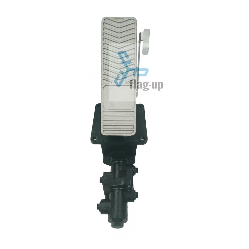
The Flag-up single-circuit pedal-operated brake valve for wheeled mobile construction machinery is engineered specifically for this duty envelope, with a proportional pedal-feel modulation, a relief-valve-protected pilot stage, and a manifold-mounting interface that integrates with the company’s pilot joystick and cartridge valve product lines.
Dual-Circuit Brake Valve Architecture: How It Splits, Why It Splits That Way, and What the Split Buys
The dual-circuit pedal-operated brake valve splits the front and rear axle braking across two independent hydraulic circuits, each with its own pilot modulation stage, its own outlet, and its own accumulator charging path. The two circuits are typically configured as a front-axle / rear-axle split, with the primary (front) circuit sized to provide 60-70% of the total braking force and the secondary (rear) circuit sized for the remaining 30-40%. Some manufacturers configure the split as a diagonal split (front-left + rear-right on circuit A, front-right + rear-left on circuit B), which provides better dynamic stability under partial-system-failure cornering — a configuration benchmarked in the UNECE transport vehicle regulations framework and the Eaton hydraulic systems portfolio dual-circuit reference designs, but the diagonal split requires more complex plumbing and is less common in the wheel-excavator class, where single-circuit architectures are documented in the Parker Hannifin hydraulic component portfolio and the Bosch Rexroth wheel brake product family catalogs.
The fail-safe behavior is the key procurement argument. A single-circuit leak in the dual architecture isolates the failure to half the braking system — the operator retains braking on the other axle, sufficient for controlled deceleration to a stop from any normal operating speed, and the mechanical parking brake is available as the final backup. This is the architecture mandated by ECE R13 for on-road homologation of vehicles above 3.5 tons gross vehicle weight, and by the equivalent GB 7258 in China. The accumulator reserve per circuit is typically sized for the same three-to-five full stops, but the two independent reserves double the total post-failure braking capacity.
The cost envelope is higher — a dual-circuit valve carries two proportional spools, two housings (or one housing with two bores), and a duplicated set of seals, which translates to a unit cost roughly 1.6x to 1.9x that of a single-circuit valve of comparable pressure rating, depending on the integrated-vs-modular design choice. The Flag-up dual-circuit pedal-operated brake valve is engineered for the 8-25 ton wheel-excavator class, with both front-axle/rear-axle and diagonal-split variants available, and a manifold-mounting interface that integrates with the company’s cartridge valve and manifold system product lines.
Filling (Pre-Fill) Valves: The Mandatory Companion to Both Architectures
The filling valve — also called the pre-fill valve — is the component that most brake valve selection guides leave out, and it is the component that determines whether the machine brakes on the first pedal application after engine start. The filling valve sits between the service brake line and the brake actuator, and its function is to convert the high-pressure, low-volume accumulator reserve into a controlled, low-pressure, high-volume pre-fill of the service brake line during the post-start window before the charging pump reaches full system pressure.
The failure mode the filling valve prevents is the soft-pedal or no-pedal first stop. Without a filling valve, the operator starts the engine, releases the parking brake, and depresses the brake pedal — but the service brake line is empty, the charging pump has not yet pressurized the accumulator to full system pressure, and the pedal goes to the floor with minimal braking force. The machine rolls. The filling valve solves this by using accumulator pressure to pre-fill the service brake line to a controlled pre-charge pressure (typically 50-70% of full system pressure) the moment the parking brake releases, so the first pedal application has full modulated braking force available.
The Flag-up hydraulic brake filling valve for excavators is engineered as a direct manifold-mount companion to both the single-circuit and dual-circuit brake valves, with a pre-charge pressure adjustment that maps to the specific accumulator sizing of the host machine. The filling valve is not optional equipment — for any wheel excavator that will be operated on a slope, in a confined work area, or in proximity to personnel, the filling valve is a safety-of-machine requirement, not a feature upgrade.
Decision Matrix: Single vs Dual Circuit by Machine Class, Duty Cycle, and Homologation Requirement
The selection decision maps to a four-axis matrix: machine-mass class, on-road homologation requirement, primary duty cycle, and load-cycle transient profile. The matrix below is the procurement team’s working reference for first-pass architecture selection.
For 6-12 ton compact wheel excavators operating predominantly on construction sites and municipal work, with no on-road homologation requirement, the single-circuit architecture is the cost-effective default — the unit cost saving is meaningful, the fail-safe exposure is bounded by the low operating speed, and the mechanical parking brake provides adequate post-failure holding. For 12-18 ton mid-size wheel excavators with mixed on-site / on-road use, the dual-circuit architecture is the safer default — the on-road homologation requirement is likely to be invoked within the machine’s service life, and the cost increment is bounded by the higher unit base cost of the machine. For 18-25 ton large wheel excavators in port machinery, mining, or heavy infrastructure applications, the dual-circuit architecture is mandatory — the machine mass, the load-cycle transients, and the typical on-road repositioning requirement all push the architecture toward dual-circuit, and the cost increment is amortized across a higher base machine price.
The diagonal-split dual-circuit configuration is the right answer when the machine spends significant time on slopes or on uneven terrain, where a front-axle/rear-axle split can produce uneven post-failure braking under dynamic cornering. The diagonal split is more expensive to plumb and to integrate, and is typically reserved for the 18+ ton class — a trade-off mapped in industry trade publications like Hydraulics & Pneumatics and the OEM Off-Highway engineering publication.
Integration with the Larger Hydraulic System: Manifold Design, Pilot Joystick, and Cartridge Valve Coordination
A brake valve does not operate in isolation — it is one component in a hydraulic system that includes the pilot joystick for travel and work-function control, the cartridge valves for pressure and flow management, and the manifold system that ties everything together. Ningbo Flag-up Hydraulic’s 20-person R&D team is organized into three specialized centers covering pilot joysticks and electronic control (8 engineers), winches and gearboxes (5 engineers), and cartridge valves and manifold systems (5 engineers), with 6-person strike teams for rapid response on custom manifold designs. This multi-center structure is the procurement-relevant point: a brake valve quote from a single-component supplier requires the OEM to integrate the brake valve with the rest of the hydraulic system separately, while a brake valve quote from Flag-up includes the manifold, the cartridge valve coordination, and the pilot interface as a single integrated package.
The integration envelope that matters for the brake valve selection is the pilot-pressure interface. The pilot joystick for travel control typically operates at a lower pressure window (10-30 bar) than the brake valve pilot (20-50 bar), and the two pilot systems are usually fed from the same charging pump through a priority valve. The brake valve selection should specify the pilot-pressure window, the pilot-flow requirement, and the priority-valve integration, and the supplier should confirm that the brake valve’s pilot stage is compatible with the host machine’s existing pilot circuit, drawing on the Mobile Hydraulic Tips engineering reference for pilot-pressure-window selection guidance. A single-component brake valve quote that does not address the pilot interface typically generates an integration problem during commissioning, with the OEM paying for the troubleshooting in field-test hours rather than in upfront engineering hours.
The manifold system integration is the second envelope. The brake valve can be supplied as a stand-alone cartridge, as a manifold-mounted valve, or as a fully integrated manifold subassembly. The fully integrated manifold subassembly is the highest-cost option but the lowest-commissioning-risk option, and is the right choice for OEMs that are sourcing a complete hydraulic control package rather than a single component. The Flag-up manifold integration team is sized for rapid response on custom manifold designs, with a typical lead time envelope measured in weeks rather than the months typical of stand-alone-valve suppliers.
Procurement Specification Checklist: What to Send the Supplier for a Clean First Quote
The single highest-impact procurement practice for brake valve selection is the specification completeness at the request-for-quotation stage. A RFQ that lists only the pressure rating and the port size produces a quote that covers only the valve, and the integration envelope (pilot, manifold, filling valve, accumulator sizing) is discovered during commissioning. A RFQ that covers the full envelope produces a quote that maps to the host machine’s architecture, with the supplier confirming the pilot compatibility — verified against the ISO standards catalogue for ISO 4413 hydraulic system general rules and the SAE MOBILUS standards database for SAE J1113 electromagnetic compatibility reference, the manifold integration, the filling valve pre-charge pressure, and the accumulator sizing as a single package.
The specification should include: machine-mass class and gross vehicle weight; maximum road speed and maximum working-site speed; on-road homologation jurisdiction (ECE R13, GB 7258, FMVSS 105, none); primary duty cycle (construction site, municipal, port, mining, road construction); load-cycle transient profile (peak bucket load, cycle time, peak slope); accumulator pre-charge pressure and total accumulator volume; pilot-pressure window and pilot-flow requirement; parking brake interface (spring-applied hydraulic-released dry disc, drum, or wet multi-disc); preferred manifold integration (stand-alone cartridge, manifold-mounted, fully integrated subassembly); environmental envelope (ambient temperature range, dust/water exposure rating, coastal vs inland). The supplier’s quote should respond to each of these envelopes, not just the pressure and port size, and the supplier should flag any incompatibility between the requested envelope and the standard product line.
The Flag-up technology team is sized to respond to this specification depth within two business days for a first-pass quote, with a follow-up engineering review of the integration envelope (pilot, manifold, filling valve, accumulator) within one week. The 20-person R&D structure — pilot joystick + electronic control, winch + gearbox, cartridge valve + manifold — is the organizational commitment to the integration envelope, validated against the EU vehicle type approval framework for on-road homologation documentation, and is the procurement argument for selecting a single supplier for the full brake-system package rather than a stand-alone-valve supplier.
FAQ
Q1: What is the fundamental difference between single-circuit and dual-circuit brake valves for wheel excavators?
A1: Single-circuit valves use one proportional spool to feed all wheel brakes from a single service line, while dual-circuit valves split the front and rear axle braking across two independent circuits, each with its own spool, its own accumulator, and its own fail-safe envelope. The dual-circuit architecture isolates a single-circuit leak to half the braking system; the single-circuit architecture loses full braking on any single-line failure.
Q2: Why do wheel excavators need a different brake valve architecture than crawler excavators or wheel loaders?
A2: Wheel excavators sit at the intersection of three braking regimes: low-speed inching precision (crawler-like), high-speed on-road homologation (wheel-loader-like), and load-cycle transient braking (material-handler-like). The pressure-window, response-time, and fail-safe envelope is the intersection of these three regimes, which is why wheel-excavator brake valve selection rarely maps to a generic off-the-shelf catalog pick.
Q3: Is a dual-circuit brake valve always safer than a single-circuit valve?
A3: Not universally. Dual-circuit is safer under single-line-failure conditions because the operator retains braking on the other axle. But dual-circuit is more complex, more expensive, and heavier, and for machines that operate exclusively below 20 km/h off-road with no on-road homologation requirement, the additional safety envelope is not cost-justified. The selection should map to the duty cycle, not default to dual-circuit.
Q4: What does a hydraulic filling (pre-fill) valve do, and why is it mandatory?
A4: The filling valve converts accumulator pressure into a controlled pre-fill of the service brake line during the post-start, pre-pump-spin-up window. Without a filling valve, the first pedal application after engine start can produce soft-pedal or no-pedal braking because the charging pump has not yet reached full system pressure. The filling valve is a safety-of-machine requirement, not a feature upgrade, for any wheel excavator operated on a slope, in a confined work area, or in proximity to personnel. The pre-fill pressure window maps to hydraulic accumulator pre-charge principles for post-failure reserve sizing.
Q5: What on-road homologation standards mandate dual-circuit braking?
A5: ECE R13 in Europe, GB 7258 in China, and FMVSS 105 in North America all mandate dual-circuit braking for vehicles above specific gross-vehicle-weight thresholds (typically 3.5 tons). The exact threshold and the test protocol vary by jurisdiction, but the architectural requirement is consistent: two independent brake circuits, each capable of stopping the vehicle alone under specified conditions.
Post time: Oct-15-2026