
Quick read:
- Open-loop proportional valves are accurate to roughly 5-8% of full-scale flow because the spool position drifts with back-pressure, fluid temperature, and pilot pressure sag.
- Adding an LVDT (Linear Variable Differential Transformer) feedback loop drops the steady-state error to under 1% and turns a proportional valve into a closed-loop flow controller that is repeatable run-to-run and machine-to-machine.
- For mobile hydraulics, the three application families that actually need LVDT feedback are precision flow control (excavator fine grading), position control (telehandler boom), and pressure control (press brake counterbalance).
- The signal chain from joystick to spool position is a 3-stage loop: command signal → coil energization → spool position → LVDT readout → closed-loop error correction.
- Five mobile machine classes where the closed-loop premium pays back: skid-steer loaders, telehandlers, concrete pump trucks, agricultural tractors, and forestry forwarders.
How Mobile Hydraulic Systems Use Electro-Proportional Valves Today
A modern mobile machine’s hydraulic system is no longer a fixed-displacement pump feeding an open-center valve bank with mechanical lever linkage. The pump is now a load-sensing variable-displacement unit, the levers are electronic joysticks, and the directional valves are piloted by electro-proportional sections that modulate flow proportionally to a current command instead of switching fully on or off like a traditional solenoid valve. The result is a hydraulic circuit that can be software-controlled, CAN-bus integrated, and tuned in firmware rather than by swapping springs.
Electro-proportional valves are the bridge between the digital command layer (joystick position, engine RPM, machine mode selector) and the analog hydraulic layer (pump pressure, spool position, actuator velocity). The valve takes a current command, typically 0-800 mA or 4-20 mA from the machine controller, and converts it to a proportional spool displacement that, in turn, meters flow to the actuator. Without feedback, this is an open-loop system: the controller asks for 50% flow, the valve gets the current, the spool moves, but the actual flow depends on how the spool actually lands, which is influenced by fluid viscosity, back-pressure from the load, and contamination in the pilot stage.
The mobile-hydraulics market has three dominant valve architectures: sectional valves (stick-built from individual sections, common on telehandlers and rough-terrain forklifts), monoblock valves (single casting, common on skid-steers and compact loaders), and load-sense proportional banks (used on excavators, wheel loaders, and forestry machines). Each of these can be ordered with electro-proportional sections, and each can be ordered with or without LVDT position feedback. The decision of whether to add LVDT feedback is the single most important cost-versus-performance trade-off in a mobile hydraulic specification, and it is also the most commonly mis-understood.
LVDT Feedback: What It Actually Does Inside the Valve
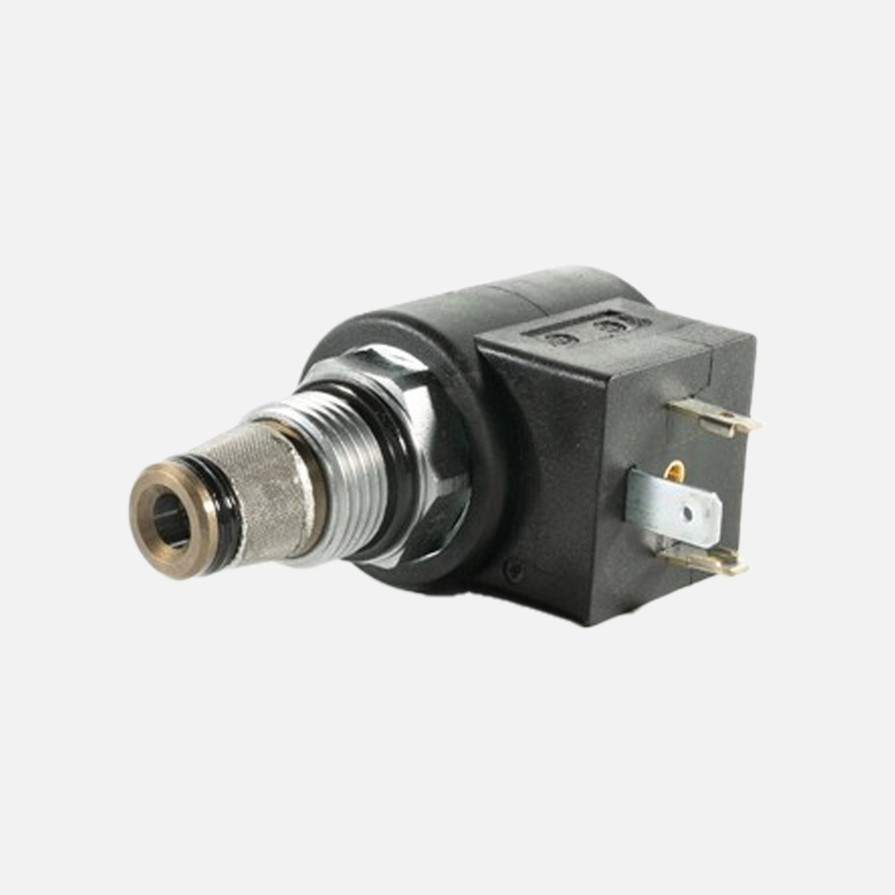
An LVDT, or Linear Variable Differential Transformer, is a non-contact position sensor built into the proportional solenoid. The LVDT’s ferromagnetic core is mechanically coupled to the valve spool. As the spool moves, the core moves through three coils of wire (a primary and two secondaries), and the differential voltage between the two secondaries is a linear function of the core’s position. The valve’s onboard electronics read this differential voltage, compare it to the commanded current, and modulate the coil current to drive the spool to the exact position the command asked for.
The signal chain is a closed-loop control loop running at roughly 100-200 Hz inside the valve, with a typical step response of 5-10 milliseconds. This is invisible to the operator but it is what separates an open-loop proportional valve from a closed-loop one. Three subtleties are worth understanding:
First, the LVDT is non-contact and the core never touches the bore, so there is no mechanical wear to worry about and the sensor’s calibration does not drift with cycle count. This is one of the reasons the technology is well-suited to mobile equipment that runs hundreds of hours per season and rarely sees a bench service.
Second, the LVDT signal is differential AC, so it rejects common-mode electrical noise. Mobile equipment is an electrically hostile environment: variable-frequency drives for the traction motors, inverters for the generator, and solenoid coils switching at high PWM frequency all inject noise into the harness. The differential AC architecture of the LVDT means that noise injected equally into both signal lines is rejected at the demodulator, leaving the actual spool position signal intact. For more on differential signaling in industrial environments, see the technical reference at Bosch Rexroth’s proportional valve engineering guide.
Third, the closed-loop controller inside the valve compensates for hysteresis, which is the single largest source of error in an open-loop proportional valve. Hysteresis is the difference between the spool position at a given current going up versus going down. A typical open-loop valve has 5-8% hysteresis; an LVDT-feedback closed-loop valve has well under 1% hysteresis, because the controller always knows where the spool is and drives it there regardless of which direction the command is moving.
Open-Loop vs Closed-Loop: The Performance Delta
The performance difference between an open-loop and a closed-loop proportional valve shows up in three measurable ways: steady-state flow error, repeatability run-to-run, and step-response time.
Steady-state flow error is the difference between the commanded flow and the actual flow when the system has settled. In an open-loop system, the steady-state error at 50% command might be 5-8% of full-scale flow because the spool is not exactly at the position the current would imply under ideal conditions. Temperature shifts the fluid viscosity, back-pressure shifts the spool force balance, and contamination in the pilot stage shifts the friction. A closed-loop LVDT-feedback system drives the steady-state error to under 1% because the actual spool position is being measured and corrected in real time.
Repeatability run-to-run is the variation in actuator position when the same command is issued repeatedly. In a precision application like concrete-pump boom control, the operator needs to know that joystick-to-actuator will land in the same place every time. Open-loop valves typically deliver 2-3% repeatability, which is acceptable for a bulldozer but not for a telehandler that is placing a pallet at head height. Closed-loop valves deliver under 0.5% repeatability, which is what most telehandler OEM specifications call for. Parker’s hydraulic valve engineering handbook discusses the repeatability and hysteresis trade-offs in detail.
Step-response time is how fast the valve moves from one commanded position to another. Open-loop valves are typically 15-30 ms. Closed-loop valves are 5-10 ms because the controller is driving the spool hard against the error signal until the LVDT readout shows the spool is at the target. For high-cycle applications like skid-steer attachment cycling, the closed-loop valve gives the operator a snappier, more predictable response.
Three Application Families That Demand LVDT Feedback
The brief’s title asks specifically about precision flow control, but in practice the mobile-hydraulics market uses LVDT-feedback proportional valves in three distinct application families. Each one has a different reason for needing the closed-loop premium.
Application 1: Precision flow control (excavator fine grading). A tracked excavator doing GPS-guided fine grading is the canonical example. The machine controller issues low-flow commands (10-20% of full-scale) to make small corrective moves as the bucket follows the design surface. With an open-loop valve, the actual flow at low command is unpredictable because the valve’s dead-band and hysteresis are largest at the low end of the spool travel. With an LVDT-feedback valve, the controller can issue a small command and know that the spool actually moved to a small position, which is what makes the closed-loop control loop in the machine controller stable. The alternative would be a high-flow open-loop valve with a separate metering orifice, which is mechanically more complex and harder to calibrate. Reference: Eaton’s mobile hydraulic solutions catalog.
Application 2: Position control (telehandler boom). A telehandler extending a boom to place a pallet at head height is a position-control problem, not a flow-control problem. The machine controller wants the boom to go to position X and stay there under load. Open-loop proportional valves are inadequate because the boom sags as the load changes and the spool position drifts with hydraulic fluid temperature. A closed-loop LVDT-feedback valve, paired with a position sensor on the boom cylinder, lets the machine controller implement a PID loop that drives the boom to the target position and holds it. Danfoss’s PLUS+1 mobile hydraulics guide walks through the controller-side architecture for this kind of application.
Application 3: Pressure control (press brake counterbalance). Mobile presses, balers, and log splitters use proportional pressure-control valves to maintain a constant clamping force as the workpiece thickness changes. An open-loop proportional pressure valve drifts with fluid temperature (which changes the spring rate of the pilot stage) and with back-pressure. An LVDT-feedback pressure-control valve holds the setpoint to under 1% across the operating temperature range, which is critical for safety-related clamping applications. Reference: Moog’s servo-proportional valve catalog.
The 3-Stage LVDT Signal Chain: From Joystick to Spool
Understanding the signal chain from operator input to spool position is the foundation of writing a correct mobile-hydraulic specification. There are three stages, each with its own characteristic time constant and noise source.
Stage 1: Command signal conditioning. The machine’s CAN-bus joystick outputs a command value, typically 0-100% of joystick deflection, that is mapped to a current command by the machine controller. The mapping is configurable in firmware and varies by machine mode (high-flow mode, fine-control mode, creep mode). The current command is then converted to a PWM signal at roughly 100-200 Hz with a 0-800 mA or 4-20 mA DC average. The PWM signal drives the proportional solenoid coil through a power amplifier in the valve’s onboard electronics.
Stage 2: Coil energization and spool movement. The proportional solenoid, energized by the PWM signal, generates a force that pushes the spool against a return spring. The spool moves until the spring force equals the solenoid force, at which point the spool is in equilibrium. In an open-loop valve, this is where the loop ends. In a closed-loop valve, the LVDT measures the actual spool position and feeds it back to the onboard controller.
Stage 3: LVDT readout and closed-loop error correction. The LVDT’s primary coil is excited by a sine-wave oscillator at roughly 2.5 kHz, and the differential voltage between the two secondary coils is rectified and filtered to produce a DC position signal. The onboard controller compares this DC position signal to the commanded position and adjusts the PWM duty cycle to drive the error to zero. The loop runs at 100-200 Hz and the step response is 5-10 ms.
A useful reference for understanding signal-chain behavior in mobile equipment is the Hydac mobile hydraulics technical documentation, which covers the noise-immunity design of proportional valve wiring harnesses. For the valve-side architecture, Bucher’s proportional valve catalog has application examples for each of the three application families above.
Five Mobile Machine Classes Where Closed-Loop Pays Back
The closed-loop premium for an LVDT-feedback proportional valve is real — typically 20-40% above the equivalent open-loop valve at the proportional-section level. Whether the premium pays back depends on the application. The five machine classes where it consistently does are listed below.
Skid-steer loader. A skid-steer with high-flow hydraulics for attachment cycling (brush cutters, cold planers, snow blowers) needs fast, predictable response. The operator expects the attachment to start and stop on a dime, and the closed-loop valve delivers that. The ROI shows up as operator-fatigue reduction and attachment-life extension. The relevant standard for skid-steer hydraulic performance is ISO 14397, which specifies the test conditions for hydraulic lift and tilt performance.
Telehandler. As discussed above, telehandler boom-position control demands LVDT feedback. The boom is a long lever arm and a small spool-position error translates to a large end-of-boom position error. Closed-loop proportional valves are standard equipment on every modern telehandler above 6-meter lift height.
Concrete pump truck. The concrete pump truck’s boom is a multi-section articulated arm that needs to position the delivery hose within a few centimeters. The machine controller is doing real-time inverse-kinematics and the proportional valves are the actuators. Closed-loop control is mandatory for the placement accuracy the application requires.
Agricultural tractor. Modern tractors with electronically-controlled implement hydraulics (hitch, PTO, remote valves) use closed-loop proportional valves to give the implement maker a predictable hydraulic interface. The Sun Hydraulics cartridge valve catalog is a good reference for the cartridge-style proportional valves commonly used in tractor implement stacks.
Forestry forwarder. A forestry forwarder is a machine that drives into a cut block, picks up a log, and drives it out. The grapple and boom are operated in a rough environment with heavy vibration and thermal cycling. Closed-loop proportional valves are required because the operator needs predictable response after the machine has been running all day in 35°C ambient.
Specification Checklist: How to Specify an LVDT-Feedback Proportional Valve
A practical mobile-hydraulics specification should cover five categories. Each one is a separate decision point, and each one has trade-offs.
Decision 1: Open-center or closed-center. Open-center systems dump pump flow to tank at low pressure when the valve is in neutral; closed-center systems maintain system pressure at all times. Proportional valves can be ordered in either configuration. Open-center is the traditional mobile-hydraulics default because it is simple and the engine can run at low RPM without the pump fighting pressure. Closed-center with load-sense is increasingly common because it saves fuel on machines that spend time idling.
Decision 2: Sectional vs monoblock vs load-sense bank. As discussed above, sectional valves are stick-built, monoblock valves are a single casting, and load-sense banks are integrated with the pump’s pressure compensator. Each has different cost and flexibility trade-offs.
Decision 3: With or without LVDT feedback. The topic of this article. Add LVDT feedback when the application demands steady-state flow accuracy under 2%, hysteresis under 1%, or step-response under 10 ms. Skip it for rough-terrain forklifts, simple attachment cycling, and applications where the operator’s hand on the joystick can compensate for the valve’s inaccuracy.
Decision 4: Current command range. 0-800 mA is the most common mobile-hydraulics standard; 4-20 mA is more common in industrial hydraulics. The machine controller’s analog output must match the valve’s input. Bosch Rexroth’s proportional valve datasheets cover the command-input options in detail.
Decision 5: Connector and harness. Mobile-equipment valve connectors are typically DIN 43650 (solenoid), DT/DTM (weatherproof), or M12 (CAN-bus). The LVDT feedback signal is typically on a separate pin from the power pins, and the harness must be designed to keep the LVDT signal away from noisy power lines.
Common Specification Mistakes (and How to Avoid Them)
Five mistakes come up repeatedly in mobile-hydraulic specifications involving proportional valves.
Mistake 1: Specifying an open-loop valve for a closed-loop application. The most common error. The machine designer assumes any proportional valve will do, and the application turns out to need the closed-loop performance. The fix is to start from the application requirements (steady-state error, hysteresis, step response) and work backward to the valve spec, not start from the cheapest valve that meets the flow requirement.
Mistake 2: Specifying the wrong current command range. 0-800 mA and 4-20 mA are both common, and a controller set to 4-20 mA driving a 0-800 mA valve will under-drive it. The fix is to check the controller’s analog-output spec against the valve’s input spec at the proposal stage.
Mistake 3: Ignoring temperature derating. A proportional valve’s hysteresis and dead-band both increase at low fluid temperatures because the fluid is more viscous and the pilot stage responds slower. The fix is to specify the operating-temperature range and check the valve’s derating curves.
Mistake 4: Over-specifying LVDT feedback. Not every application needs it. Adding LVDT feedback to a simple on/off dump valve wastes money. The fix is to evaluate the application requirements first.
Mistake 5: Under-specifying the harness. The LVDT signal is sensitive to electrical noise. The fix is to use shielded cable for the LVDT pair, separate the LVDT wiring from the power wiring, and ground the shield at one end only.
FAQ
Q1: What is the difference between an electro-proportional valve and a proportional solenoid valve?
A1: The terms are often used interchangeably, but technically the electro-proportional valve is the complete valve assembly (spool, body, proportional solenoid, optional LVDT), while the proportional solenoid is just the electromagnetic actuator that drives the spool. A proportional solenoid can be ordered separately and installed on a compatible valve body, but the closed-loop performance is only available when the solenoid has an integrated LVDT and the valve has the onboard electronics to close the loop.
Q2: How fast is the LVDT feedback loop inside the valve?
A2: Typical closed-loop bandwidth is 100-200 Hz with a step response of 5-10 ms. The bandwidth is set by the LVDT’s excitation frequency (around 2.5 kHz) and the onboard controller’s sample rate. Higher bandwidth is possible but rarely needed for mobile hydraulics because the downstream actuator (cylinder or motor) has a much slower response than the valve itself.
Q3: Can an LVDT-feedback proportional valve be retrofitted to an existing machine?
A3: Yes, in most cases. The valve is a drop-in replacement for the open-loop valve, and the wiring harness needs the additional LVDT pair (typically two extra pins on the connector). The machine controller’s firmware may need to be updated to support the closed-loop mode, but most modern controllers can be re-flashed in the field.
Q4: What is the difference between LVDT feedback and other position-sensing technologies?
A4: LVDT is the dominant technology for mobile-hydraulic proportional valves because it is non-contact (no mechanical wear), immune to common-mode electrical noise (because it is differential AC), and relatively inexpensive. Other technologies like magnetostrictive and Hall-effect sensors exist but are more common in industrial hydraulics than in mobile equipment.
Q5: Does LVDT feedback help with valve diagnostics?
A5: Yes. The LVDT signal can be monitored by the machine controller, and an unexpected pattern (e.g., the spool not reaching the commanded position) is an early indicator of a failing solenoid, a contaminated pilot stage, or a worn spool. The closed-loop valve is essentially self-monitoring, which is a maintenance advantage.
Post time: Oct-10-2026